Perch Lake Lumber Company, Is No Longer
A Narrow Gauge Layout
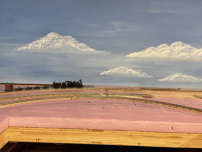
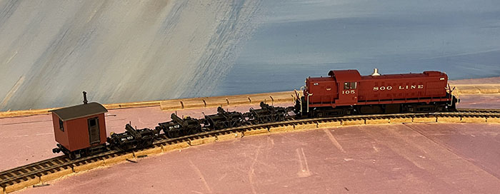
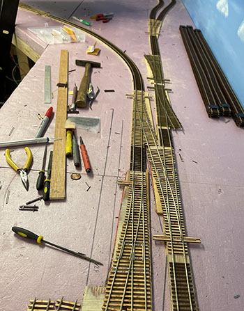
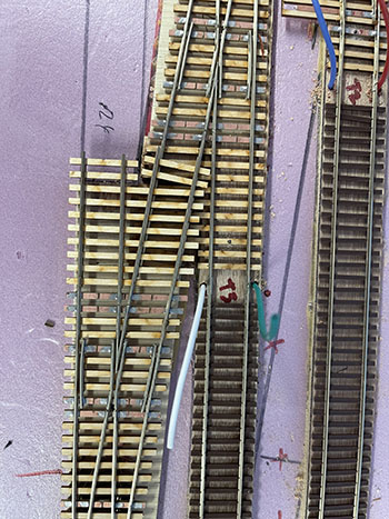
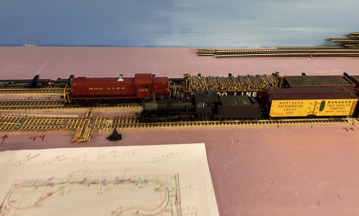
The Perch Lake Lumber Company in conjunction with the SOO Line has gone Standard Gauge. During the end of 2020 and into 2021 I decided that the little engines were all little too little. I also have a full Standard Gauge lumber set of equipment which has gone unused for a few years as we run transition era and new WC on my Glen Ellyn Layout. Starting summer 2021, I removed the narrow-gauge track and widened the roadbed to standard gauge. I built #5 and # 6 turnouts and had plenty of Micro Engineering Code 83 track. The railroad is up and running with 3 trains on the line using ground throws that I installed after checking with the club's ground throw expert Jack Zimmer. Ground throws will be used on the entire layout. Due to agreement with the SOO Line, all blocks will have signals via LCC detection transformers.
Old Updates below:
3/22/21
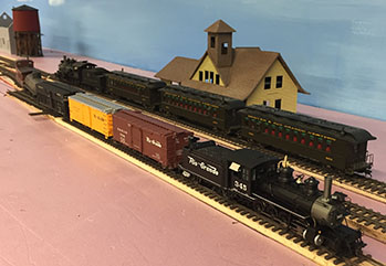
Operational testing and switch work.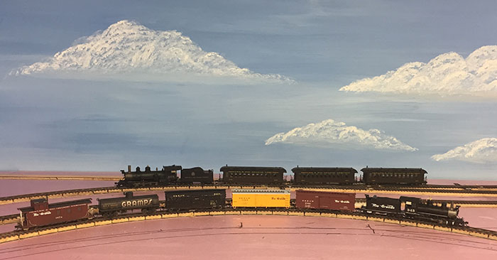 Two train operation around the layout.
 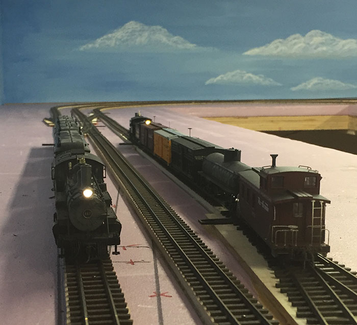 Backing into the sidetrack while the Passenger train is cleared.
9/24/20
Full circle operation of the layout. 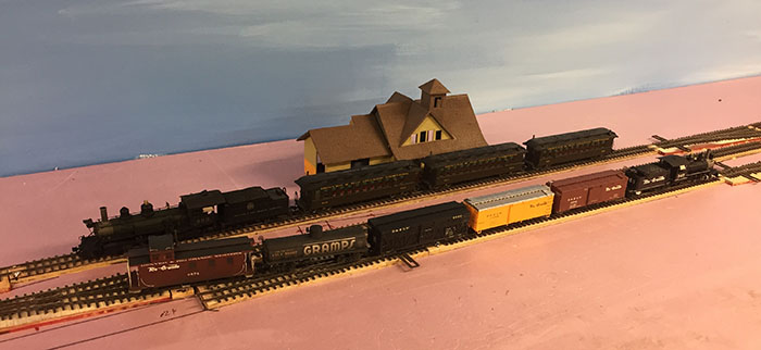
I finished the locating of a shorted turnout and then rewired all I had to remove to get things going again. I added the second reverse loop auto controller and completed the wires around the layout.
I was able to run the C19 with a short train around in one direction and then manually throwing turnouts reverse the direction of the train.
Turnouts need cleaning and some touchup of the clearance from painting, but the train got around the whole layout.
The passing siding (T8) still needs some track, but the guest refrigerator is blocking the access to the area with the lean over. Only main line is in place and the line to the staging is in place.
No sidings installed but their turnouts are in place. Building a layout in quarantine meaning all by my self is difficult as I have only phone connections to bounce ideas off other modelers.
The reverse loops have their own controllers and are on their own power breaker. I am using old Tony's Train Exchange reverse loop controllers with PSX breakers. Each segment has drops but at this time all are connected. I want to get trains running so I can find problems o in the turnouts as I get ready to put in the motors.
*****************************************
9/12/20
DCC Operational
Wires going in under the layout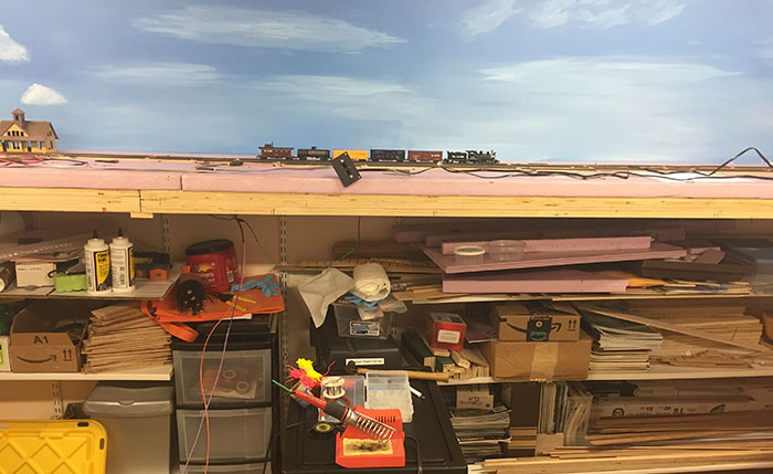
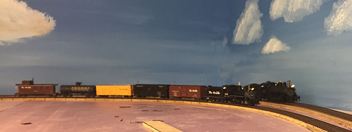
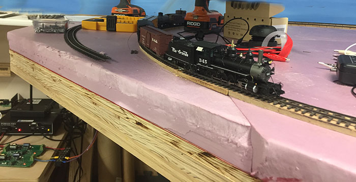
Progress 8/28/20 Can't do more without wires:
8/15/20
All Roadbed for the mainlines are in with switch blocks and crossovers placed and the entire roadbed sanded ready for track. The track is painted and weathered, but needs the of the railhead and connection points cleaned off.
Turnouts have been painted and weathered and cleaned electrically tested, but also need the contact locations cleaned and the frog wires attached.
******************************************************************
Turnouts 7/10/20 update below:
Roadbed 7/8/20
Upper Left Framework 6/19/20
Instalation of the Upper Left table top 6/20/20
Reach for the Back or Up Underneath 6/24/20
New layout update with additional turnouts
7/15/2020
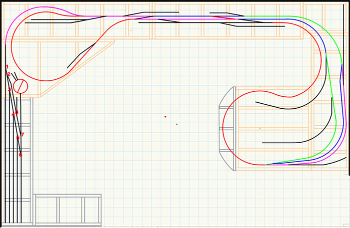
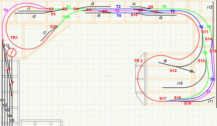
I have added additional sidings in the town and given the turnouts numbers.
Black on the main Blue in the industries and Red in the yard.
Turnouts put onto ties, an outdoor project. 7/10/20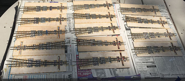
*Roadbed 7/8/20*
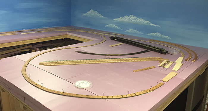
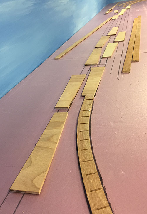
Wooden roadbed gluded to the foam for the loop and the ard lead. I also made 30 Turnout roadbed blocks today.
The use of Circuitron Remote Tortoise Mounts 6100 and 67101 will allow me to mount the motors below the layout and only have a 1/16" hole from the roadbed down to the underside of the layout. No need to cut 2" square holes in the foam or shelves and no need to build Tortoise Mount roadbed for each turnout.
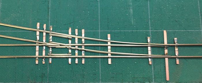
Working on Code 70 #6 HOn3 Turnouts
Building the smaller gauge turnouts with .070" rail is not as easy as HO Standard gauge with code 83 .083" rail. The ties are smaller on the HOn3 turnouts and I needed a fine pointed soldering iron.
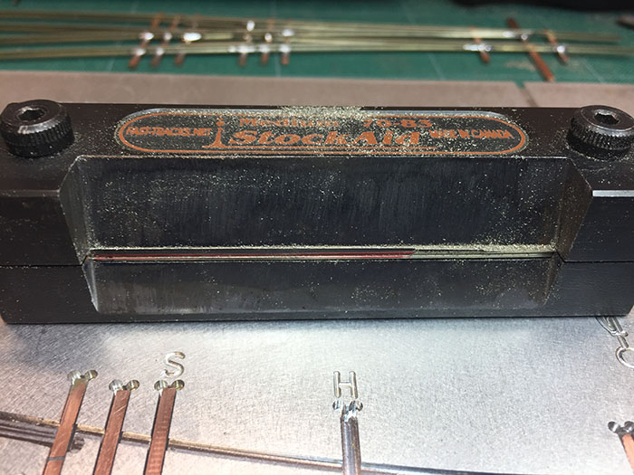
I did review the videos from Fast Tracks and used the Stock Aid Tool.
This tool helps you take the bottom of the stock rail off to clear the point rail without harming the main part of the rail. By marking the area to be filed off with a marker you can taper the edge as you clear the area needed by the point rail.
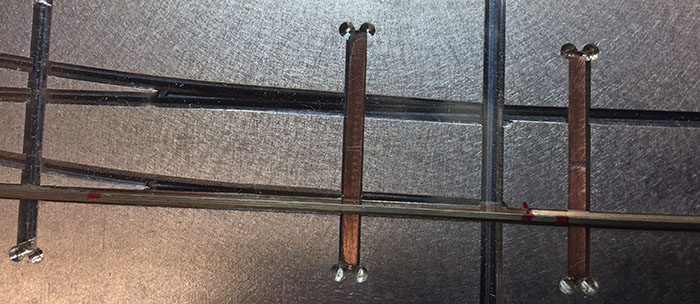 Here you see the space between the red dots that has had the base of the rail removed and also see the clearance for the point rail.
My first turnout looked and operated like I had not built a turnout before but after reviewing the process and getting my magnifier light, so I could see, I was able to repair my errors and have a finished turnout that meets the NMRA standards.
My second turnout was much better and now that I have a new set of fine points for my soldering iron, I am ready to build more (21 more). Another reason I used the Stock Aid is that the belts on my 1X30 inch belt sander we all use to remove the base of the rail had all aged such that the adhesive on that held the belts together was dried out and the belts were coming apart. one caught a code 70 rail and made it look like a pretzel. I have purchased new belts today.
Parts for 6 more #6 HOn3 Turnouts ready for assembly into 4 Left and 2 Right. (6/28/20)
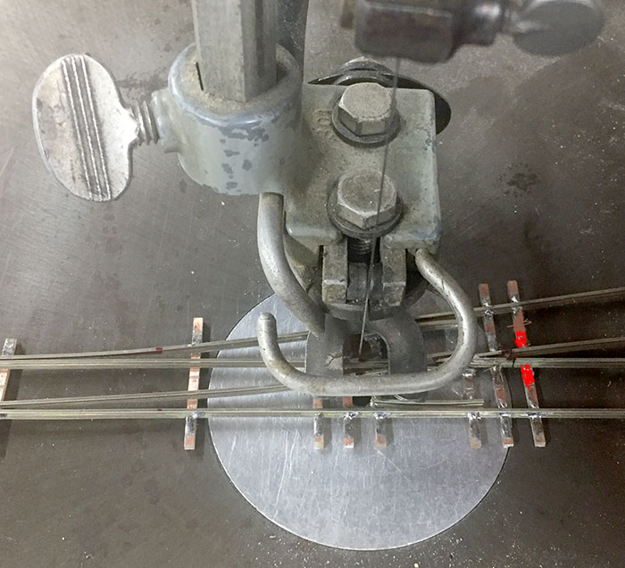
With all assembled on Monday 6/29/20 I took then to the Delta 24" professional Jig Saw for insulating the frogs.
I have found an issue with the HOn3 turnouts that we have not seen with HO turnouts. The area in Red shows the rails cut before the last tie. The clean cut was no problem but because of the lack of space and the insulation cut in the copper of the PC board tie there is only solder on one side of the rails and the PC board tie copper is broken for insulation. This causes the frog point rails to be very fragile. Only 1 of the 34 rails I cut came off on the saw I had 3 more brake in moving the turnouts back to the modeling bench. I will use a 3-point track gauge to replace the rails and plan on adding PC ties on each of these turnout tracks in the Quick Sticks that hold the rails. On a HO turnout the space between the rails at this point is wide enough to have solid solder joints on both sides of the rails and have an insulation cut on the top of the PC board tie. (6/30/20)
Getting Ready for 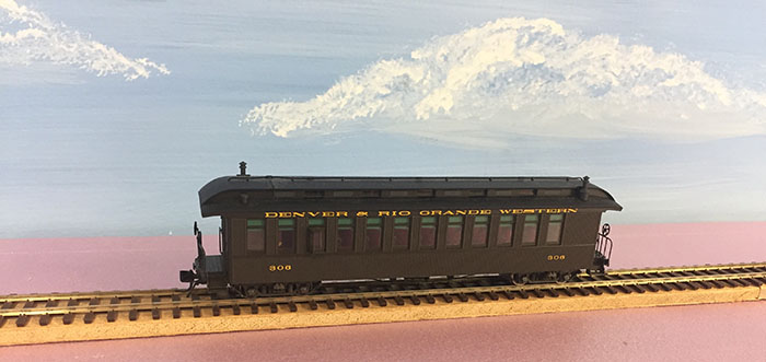 Track
Track
I found I had an issue with the roadbed I had made for the layout as dual gauge
Below on the top is the HO roadbed in 8' lengths for dual gauge service. On the bottom is the new sized roadbed cut to 1" after many talks with members and some math checking on roadbed size for HOn3 I decided that the HO was 25% to wide.
Dealing with 8' lengths 1/2 of which were cut every inch for making curves presented me with a problem in ripping it to 1". My solution was to layer a curve able section between a solid straight section, stacking to 7 layers. The length of 8' was also an issue as I was going to rip these on a Radial Arm Saw. I decided to cut the sections in half and then rip them. To hold them together I used 1.25"brad nails. This presented an issue as I could not take them apart after ripping. I took great care in the placement of the nails and will use the chop saw to remove the first and last inch which has the nails.
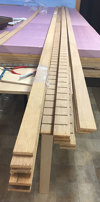
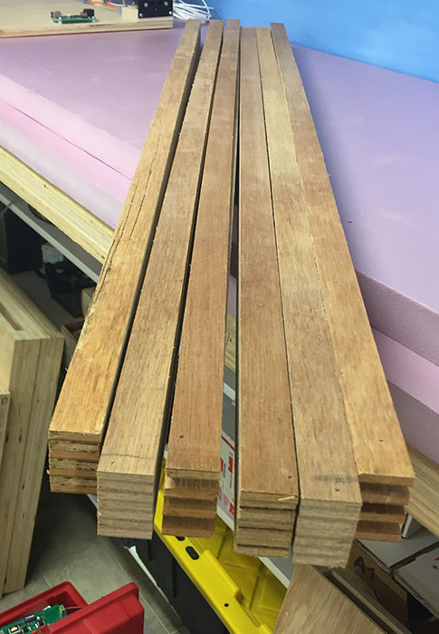 Cleanup took longer than the wood work !!!
Progress continues 6/18/20
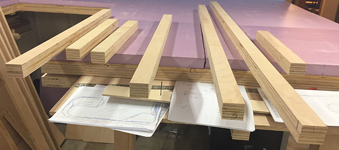 Framework for the upper left connection to the shelf
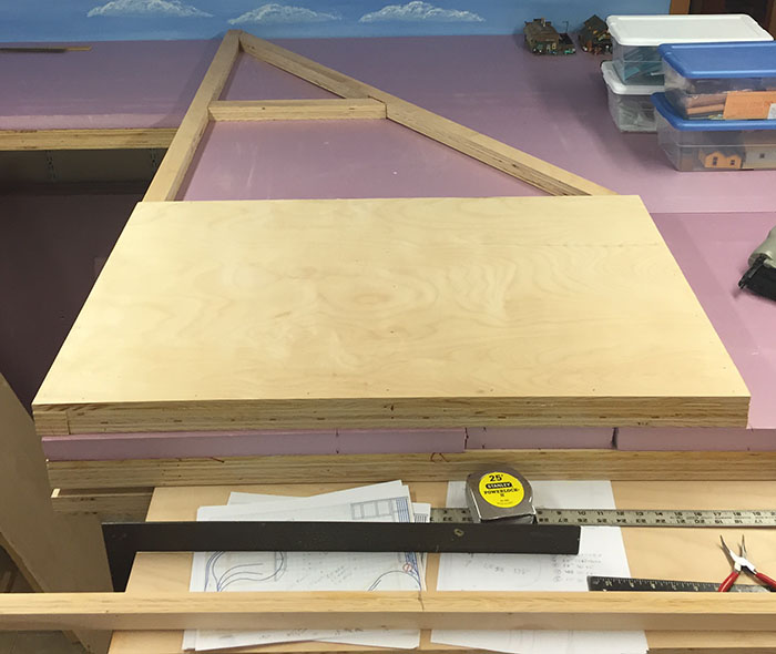 With the wood cut I had to attach the plywood. The new extension provided a workbench that allowed me to work standing up rather than crawling on the floor. This made gluing and nailing much easier and I could use the square rather than the lines on the floor.
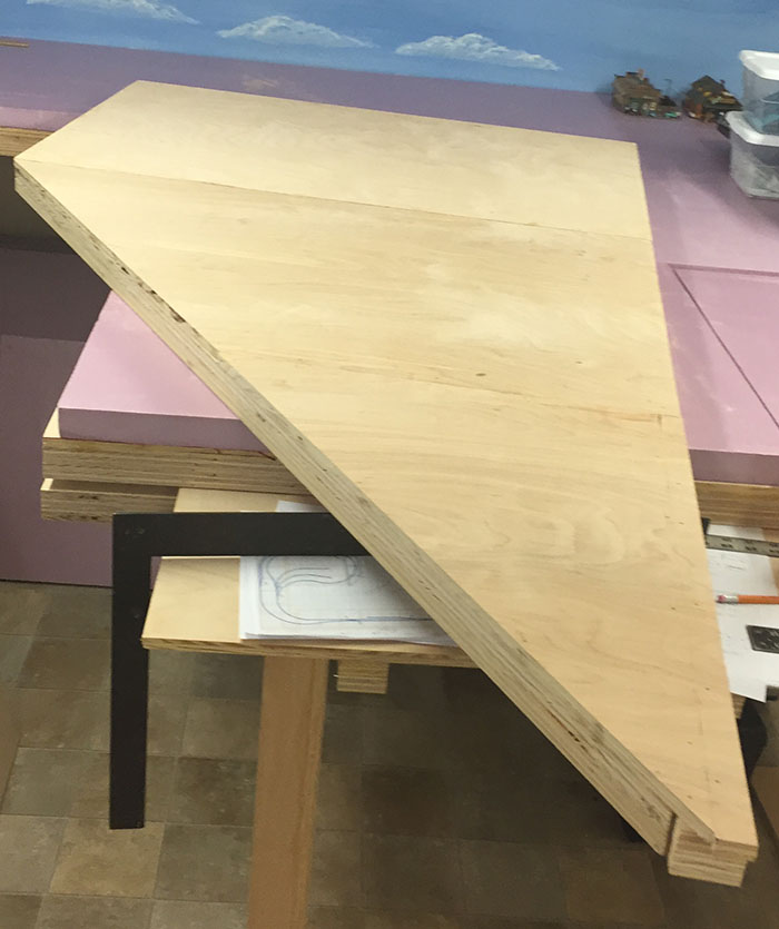 This is the insert as the glue is drying. It still needs a little sanding and the point needs to be cut off.
Below is the underside showing the bracing.
It is flat and square but the pone camera in my left hand distorts the shape a bit.
Putting away the tools and reinstalled the shelf above the desk ready for the yard leads that will come odd this section.
I added a temporary shelf above the desk to hold items that will go on the new shelves when we find the correct 12" bullnose shelving.
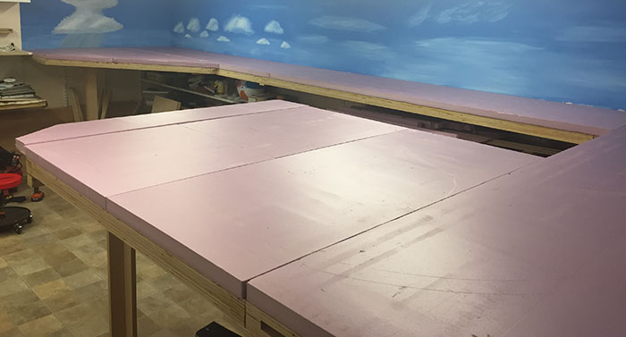
The layout table is ready!
Around the Room
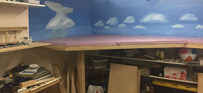 The final addition connects to the shelf on the left.
To be able to do this requires that I build the layout. While the 2 wall shelf units have been built for years, other module activities and club work on modules for the Division convention and the Make It! Camp has kept me busy. Isolation has provided time for layout construction.
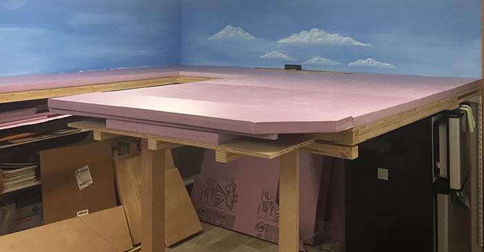
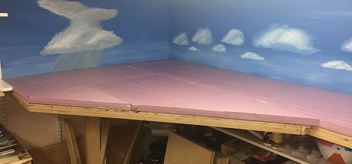
Over the last week I have been able to build the extension of the layout that includes the lumber and mining areas. This are is basically 4.5’ X 5’ with a curved end having a rock wall with a curved trestle.
Construction has used available lumber which had a purpose long forgotten. But the furniture grade quality allowed me to make the necessary elements for construction.
I did have to relearn the proper way to rip lumber on a radial arm saw. As Sharon will testify, I have come a long way in ripping with this power tool. I have been Inside and outside ripping lumber of 328’ liner feet with the saw which a few years ago took much prodding for me to even think of. I was not comfortable ripping with a tool that I have used for years to crosscut and dado. Just an aside this is the Radial Arm Saw I received from Keith, after the Elmhurst flood on Spring Road, and rebuilt and upgraded into service with Sears Craftsman replacement parts.
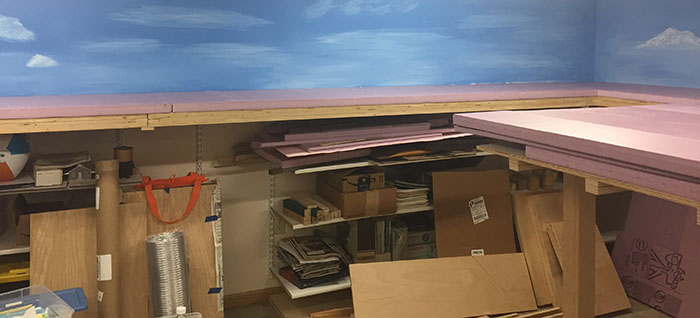
I have also added a staging yard to the layout on a shelf over the work bench and Ham Radio equipment. This will allow me to store trains and operate with more than a fancy loop. While Lumber and some mining will still be our main operation tourism has brought the need for more provisions into Perch Lake and so we will be having mixed trains serving on our now Common Carrier Line.
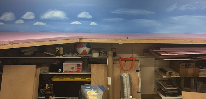
I have a small section to build out between the lumber mill and the staging yard but have all the wood to finish this section. I have decided to raise the shelves over the work desk and also use the lowest shelf for the staging yard as this does not require me to venture out and purchase the 2 replacement shelves that will replace the ones used for the yard. A side benefit is that the lighting mounted on the shelves will not have to be moved but will provide better light for model building.
Backgrounds will be printed when the Fab Lab Three Lakes reopens but until then I have the painted sky to work with.
I have the Demo /Test Module for LCC along and can use it to hook up to the layout. Here it is without the power supplies and NCE PowerCab in place.
With the LCC system I can detect the blocks and control all mainline turnouts.
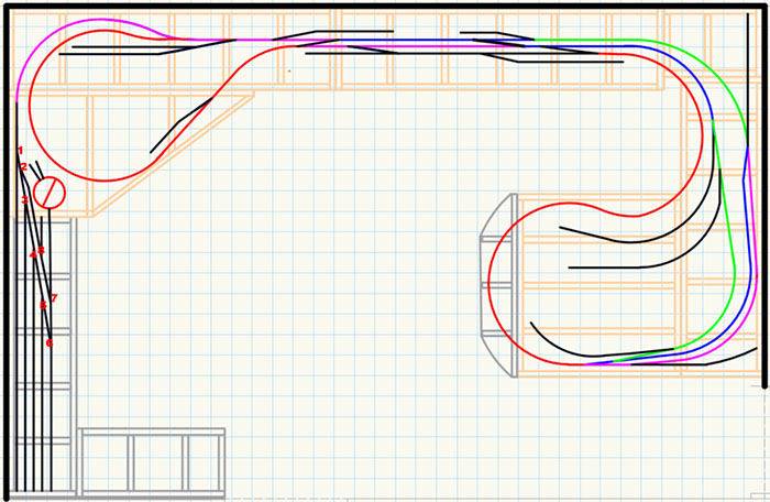
Perch Lake Lumber Company Layout in HOn3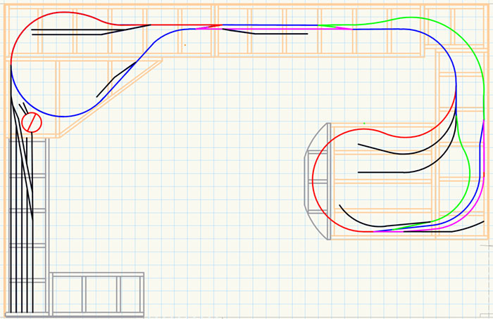 Layout Design, each square =6"
The colors are for block detection
2010 Standard gauge design ( the old days )
Please remember to keep your locos running. Get the locomotives out and run them to test and keep the grease from turning to glue.
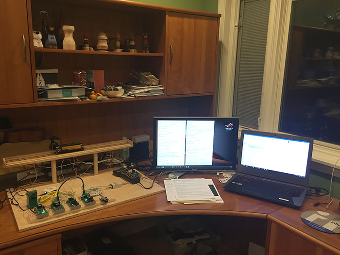 The new configuration of my upstairs office
 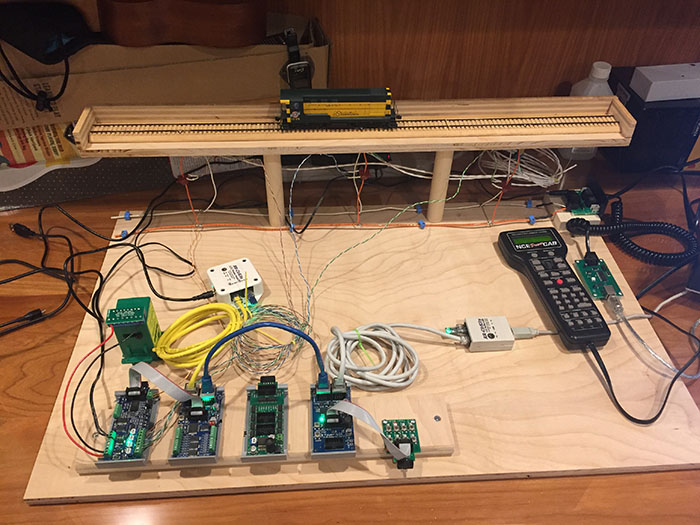 This is the New Demo / Testing Lab for DCC, LCC and Arduino.
The Demo / Testing Lab is designed to having 3 blocks on the track to test detectors and allow for programming and testing locomotives.
DCC is supplied by a NCE PowerCab with a USB interface to JMRI. This allows me to program and test locomotives and well as experiment with WIFI connections via JMRI.
The LCC system is set up with, from left to right, A BOD4-CP, control point, a Signal LCC interface card, an 8 output Stall Motor Driver (SMD-8), a Tower LCC Interface card, and an I/O Test board. All these components are from RR-CirKits, Inc. An LCC USB Buffer connects the LCC network to the computer for configuration.
The Orange wires feeding the blocks with DCC have a Current Transformer (CT) that detects current passing thru the orange wire and reports back to the BOD4-Control Point (CP). The White wires have NCE BD-20 Detectors that work with the Arduino Signal System that we use on the TLMRC Modules and teach at Make It! Camp.
There are currently power supplies for the PowerCab, LCC and the Switch machine.
The locomotive may be controlled by the PowerCab or JMRI cabs as it moves across the track each block that is occupied will show up on the BOD4-CP via a LED. If I have the network monitor screen active on the computer I will also see all communication between the LCC nodes. This allows me to view the events that any change in the track or the pushbuttons on the test board create as well as the events that are a result of the events that occur. (The train enters block 1 and the event ending in o7 is displayed but that event (occupancy of block 1 causes the signal board to send an event to the turnout control to move the turnout motor) an event ending in 31. MT01: 02.01.57.01.10.75.00.31
Thanks to Daniel Kubarych of the ARHS for his guidence on the configuration of this project.
We see the loco in block2 the yellow light is on indicating the block is occupied and the red LEDs are flashing.
When the loco moved into block3 the Green light came on and after it cleared block 2 the yellow light went out and the Red LEDs stopped flashing.
Working all alone during Isolation
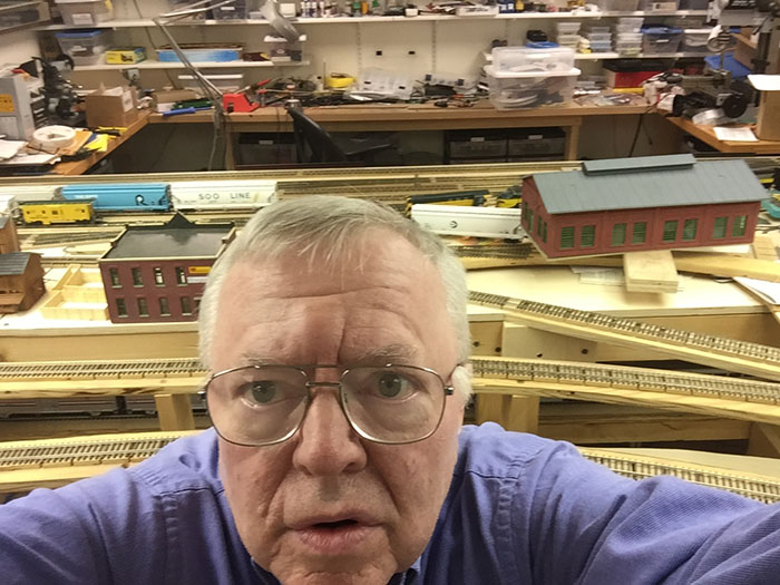 Why Do I look Like This?
 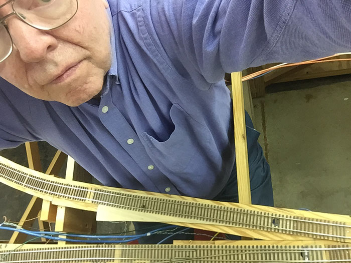 Because I am in here with my close-up glasses on.
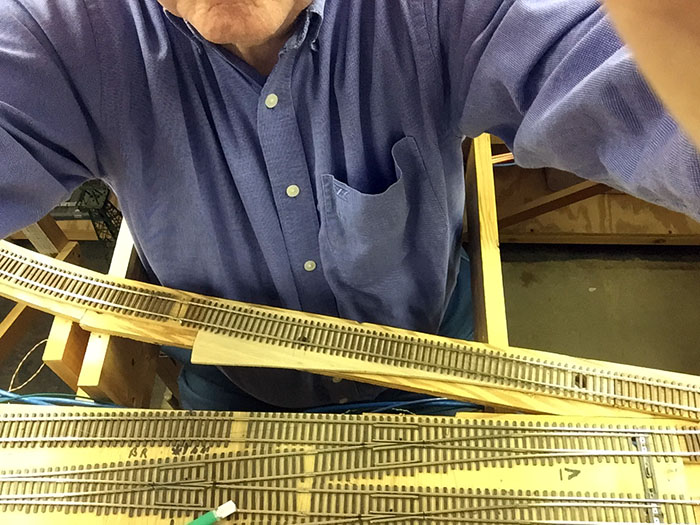 In order to replace the track in front of me
 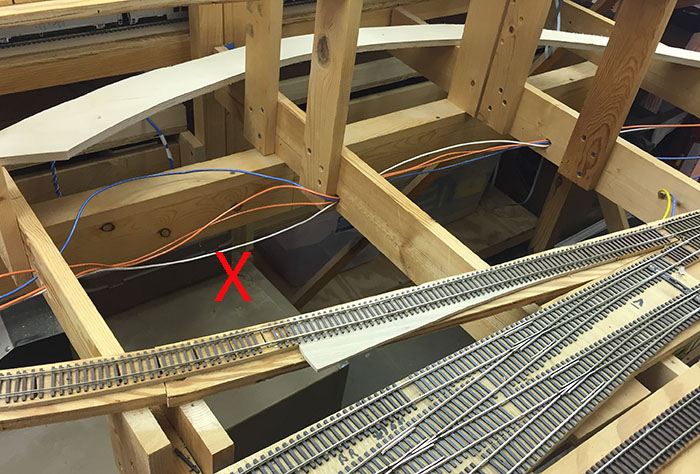 The Red X Marks the Spot where I was working. The issue was that I had to replace a section of track that was code 70 where there should have been code 83. I believe we added that section of track where a #8 turnout will go later. The code 70 was mixed with the remaining code 83 while we built Rhinelander Yard that has code 70 rails. There were bumps going in and out of that section of track.
 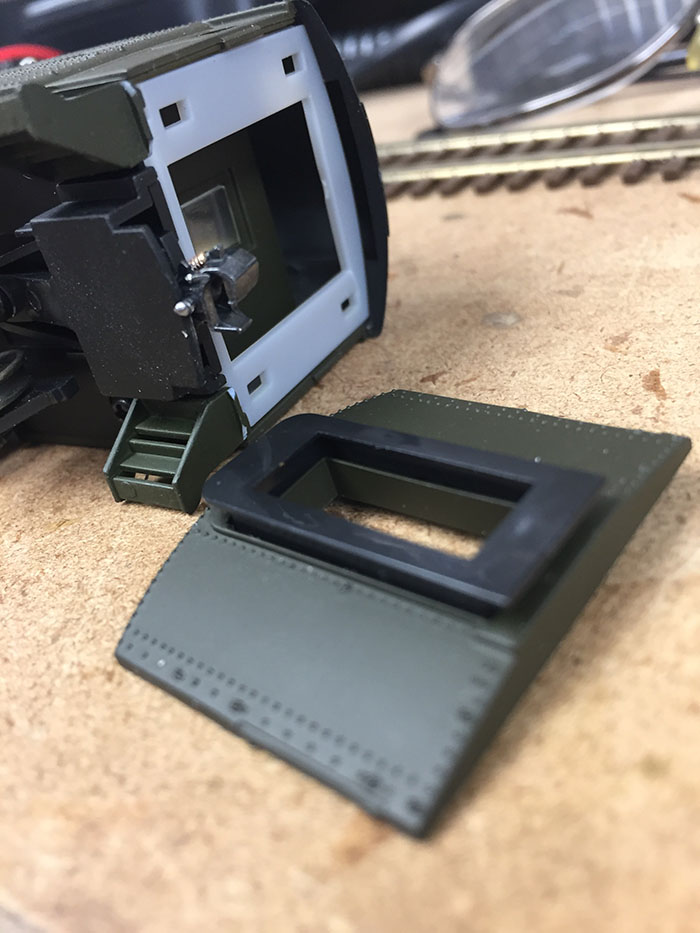 Back on 3/21 this car, in the middle of a train, left the track and hit the floor. The cars in the train ahead of this one kept going and the ones behind just stopped on the track. 3 of the 4-wheel sets from this car flew across the floor and had to be searched for. Looking for a reason that this car would have departed the rails I only found the section of code 70 track between code 83 that could cause a car to derail. Replacement was the only answer. Because we are all on our own these days, I moved all the tools I might need onto the Bradley Yard so I could do the track work with only 2 trips under the layout. I also spiked the yard tracks while I was under the layout and cleaned the points on the commercial turnouts at that end of the yard. I believe the corrosion that showed up in between the points and stock rails contributed to locomotives stalling at that location. In addition, I found that I had wired the #8 turnout with 8 conductor wire but had yet to wire the frog. I have setup the parts and tools to correct this which should help the movement thru this section of the main line. I have also found that the commercial turnouts from Walthers frogs are able to be connected and conduct around the plastic insulation. I am installing frog power wires and new connectors to the Tortoise switch machines to power the frogs at that end of Bradley yards. .010" Evergreen plastic is inserted into the green connectors to prevent them from sliding sideways and shorting the SPDT sections. CAT 5 wires connect the turnout socket to an eight-connector barrier strip for each turnout.


